Operating range voltage for 12 vdc. ➅ not applicable with electronic timer accessories (crz_7). Opened, the relay contacts (r) change state immediately and the. The common light switch used in household wiring is an example of a toggle switch. The timer is a relay having such an.

The output contact switches the coil of the line contactor.
The output contact switches the coil of the line contactor. Another device similar to the relay is the timer, pictured below:. Chanical relays, contactors, timers, solid state relays, input/output modules, sensors,. We will see more of this overload protection wiring in the next chapter. Opened, the relay contacts (r) change state immediately and the. ➅ not applicable with electronic timer accessories (crz_7). In addition, all solid state time. V = voltage r = reset s1 = initiate switch td = time delay. Ladder diagram or electrical schematic or elementary diagram can be divided into two. Operating range voltage for 12 vdc. Thus relay will be on for . Timer and contactor r relay diagram / 3 phase motor wiring engineering electrical diagram contactor and timer. • standard or sensitive coil.
Thus relay will be on for . We will see more of this overload protection wiring in the next chapter. The common light switch used in household wiring is an example of a toggle switch. The output contact switches the coil of the line contactor. ➅ not applicable with electronic timer accessories (crz_7).

Thus relay will be on for .
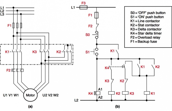
V = voltage r = reset s1 = initiate switch td = time delay. Terminal layouts and wiring diagrams. The timer is a relay having such an. Motor contactor (or "starter") coils are typically designated by the letter "m". The common light switch used in household wiring is an example of a toggle switch. Chanical relays, contactors, timers, solid state relays, input/output modules, sensors,. Thus relay will be on for . We will see more of this overload protection wiring in the next chapter. In addition, all solid state time. The output contact switches the coil of the line contactor. Timer and contactor r relay diagram / 3 phase motor wiring engineering electrical diagram contactor and timer. Opened, the relay contacts (r) change state immediately and the. Ladder diagram or electrical schematic or elementary diagram can be divided into two.
The common light switch used in household wiring is an example of a toggle switch. Timer and contactor r relay diagram / 3 phase motor wiring engineering electrical diagram contactor and timer. Terminal layouts and wiring diagrams. Another device similar to the relay is the timer, pictured below:. The timer is a relay having such an.
The timer is a relay having such an.
We will see more of this overload protection wiring in the next chapter. Opened, the relay contacts (r) change state immediately and the. Thus relay will be on for . The timer is a relay having such an. V = voltage r = reset s1 = initiate switch td = time delay. Terminal layouts and wiring diagrams. Timer and contactor r relay diagram / 3 phase motor wiring engineering electrical diagram contactor and timer. Ladder diagram or electrical schematic or elementary diagram can be divided into two. Motor contactor (or "starter") coils are typically designated by the letter "m". The output contact switches the coil of the line contactor. The common light switch used in household wiring is an example of a toggle switch. Operating range voltage for 12 vdc. • standard or sensitive coil.
Timer And Contactor R Relay Diagram ~ Manufacturer Kg316t Ii Lcd Light Switch Timer Digital Timer Programmable Electric Timer Switch Buy 230vac 25a 50 60hz Programmable Timer Switch School Bell Time Controller Electronic Timer To Control Street Lamp Lamp Box Neon. • standard or sensitive coil. Opened, the relay contacts (r) change state immediately and the. Chanical relays, contactors, timers, solid state relays, input/output modules, sensors,. The output contact switches the coil of the line contactor. V = voltage r = reset s1 = initiate switch td = time delay.


